Printed circuit heat exchangers
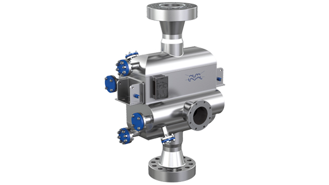
Alfa Laval printed circuit heat exchangers (PCHEs) combine superior robustness and integrity with exceptionally high heat transfer rate in a unit up to 85 % smaller and lighter than traditional shell and tube exchangers. The unique design results in excellent performance, lower installation and operational costs, and improved safety. Each unit can be fully customized according to the exact needs of the customer.
Applications
The PCHE is designed specifi cally to deliver un-paralleled compactness and efficiency in clean and high-pressure duties, that are beyond the capability of other welded plate type heat exchangers, with design pressures ranging from vacuum to 650 barG (9,430 psiG).
Typical marine applications are, High Pressure Vaporizer in fuel gas supply systems and gas heating/cooling duties in reliquefaction systems on LNG carriers.
Technical data
Design pressure
CE/PED Vacuum to 650 barG (9,430 psiG)
ASME Vacuum to 650 barG (9,430 psiG)
Design temperature
316L SST –196°C (cryogenic) to 800 °C
(–321°F to 1,472 °F)
Connections
2–30 inch typical, customizable
Standard materials
316L SST (other materials available on request)
Dimensions/Weights
On request tailored towards requirements, ranging from a few kilograms to tens of tons
PCHE benefits
- Exceptional savings in footprint, volume, weight and structural support costs
- Extensive capacity range
- Design temperatures from cryogenic to 800°C (1,472°F) and design pressures up to 650 barG (9,430 psiG).
- Exceptionally high heat transfer rate for maximum operating efficiency
- Safe to operate – no pressure relief valve needed
- Easy maintenance ensures maximum uptime
- Diffusion bonding opens up for full customization possibilities in terms of fluid channel design pattern
Darbības pamatprincipi

Working principal
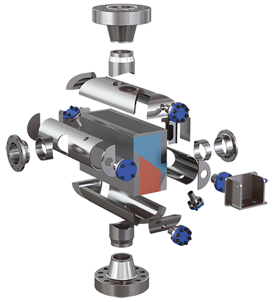
The PCHE operates with two or more media on opposite sides of a bonded plate. It is possible to have high-pressure fl ows on both sides. The 2 or 3D pattern is optimized to give the required thermal length and pressure drop.
Design
The PCHE has a complex fl ow pattern chemically etched on fl at sheets of material. This flow pattern is optimized for each specific customer duty to give the required thermal and hydraulic characteristics. Each flow circuit plate pattern can be different giving the possibility of asymmetric flows and optimized 2-phase behavior. The individual plates are then stacked into a block and diffusion bonded, in a state-of-the art furnace, at high temperature and pressure. Multiple blocks can be welded together to create the required thermal capacity or HTA (heat transfer area). Inlet and outlet flow manifolds, customer connections and (if required) connections for drain, ventilation or cleaning are welded onto the completed core to finalize the heat exchanger. Design pressures of up to 650 barG (9,430 psiG) in 316L SST are achievable with this confi guration. Heat transfer surface areas are tailored based on requirements.

